Calculations & Measurements
VIBRATION MEASUREMENT
CFM Schiller offers vibration measurement services at your location.
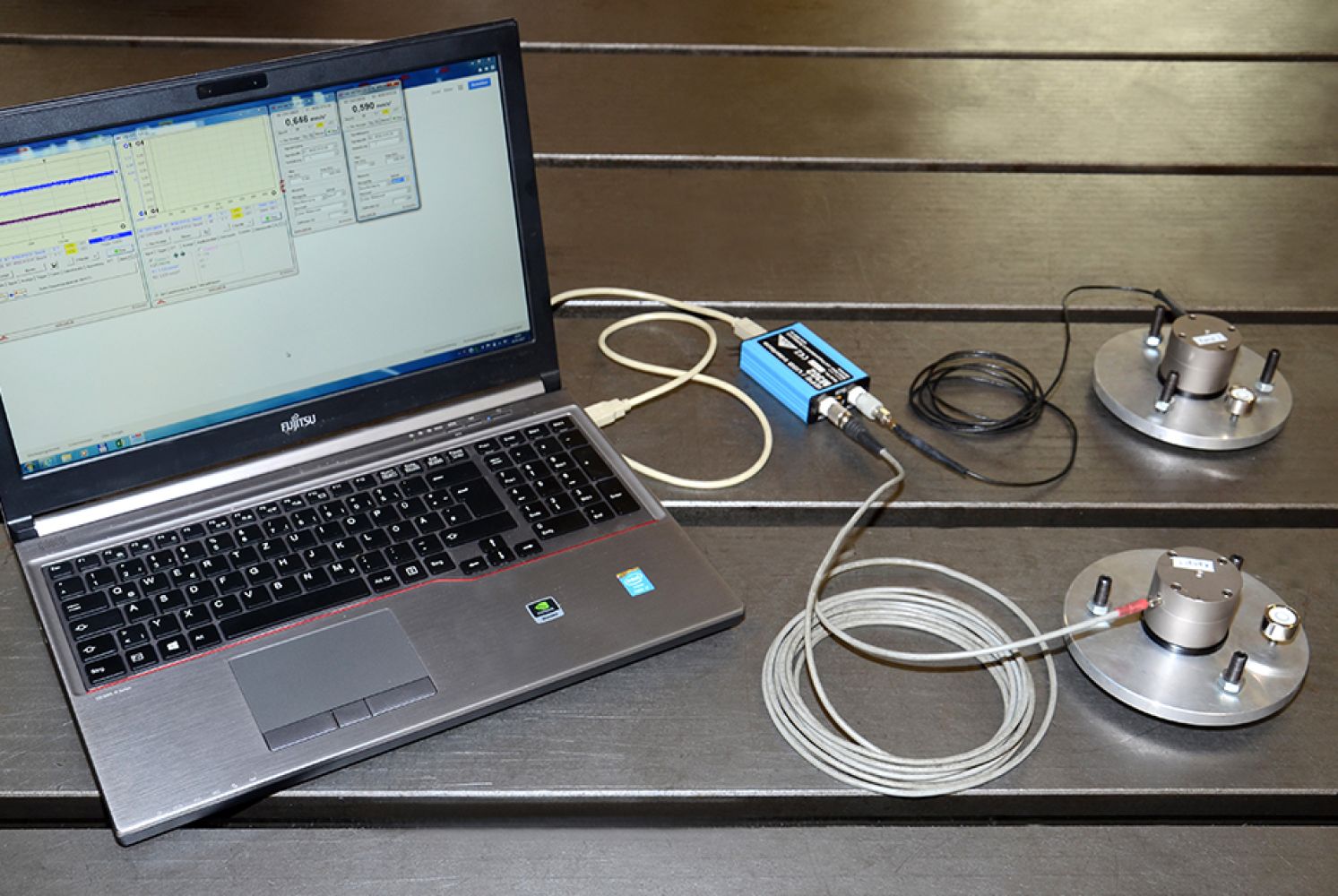
A passive vibration isolation protects machines and devices from exterior vibrations. It is necessary to know which vibrations are transmitted from the surroundings to the machine at the distinct location of installation. Based on these measurements, CFM Engineers will determine whether and which type of vibration isolation is required for your very application.
The vibration measurement and the subsequent evaluation determine the oscillation velocities against the frequency band. The measurement is conducted with accelerometers, one for each coordinate direction x, y, and z. The measurement results are evaluated and summarized in a short report.
When the measurement results are available, CFM Schiller will provide a non-binding quotation for the suitable vibration isolation system.
SEISMIC MASS PLANNING
CFM Schiller individually designs your vibration isolation – tailored to your technical and economic requirements.
A rigid body model is used for computer-aided calculation of oscillation amplitudes and velocities as well as the degree of isolation. We require the expectable static and dynamic loads during operation as well as the frequency band, in which the plant will be operated, from you. Further necessary boundary conditions are shape, position, and weight of superstructures on the seismic mass.
Based on these physical parameters, CFM Schiller will configure the vibration isolation. This procedure determines the shape and weight of the seismic mass and the type of vibration isolation – whether air springs or steel springs, additional volumes, and dampers are applied or not. We also take the existing infrastructure, spatial limitations, and underground properties into consideration. From the first layout phase on, we apply measures for effective implementation of plant operating safety.
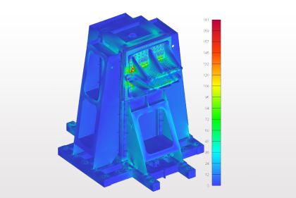
FINITE ELEMENT ANALYSIS
For the layout of vibration isolation systems and test rig components, CFM Engineers apply modern FEM calculations. Parts and assemblies are iteratively designed based on static and dynamic analyses. Additionally, CFM Schiller offers the service of finite element calculations to enhance your own products.
Vibration Isolation Technology
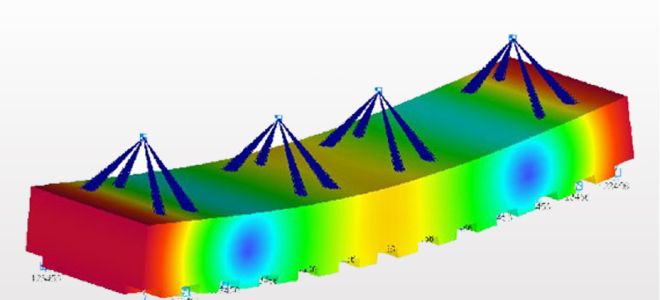
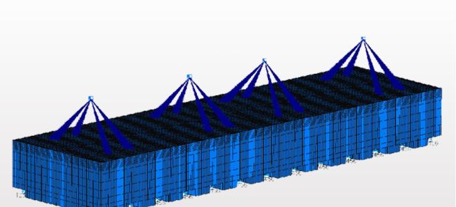
Planning and layout of seismic masses is based on calculations with a rigid body model. In the subsequent steps, both the concrete foundation and the clamping plate are analyzed and optimized with different FEM calculations. This procedure guarantees a functioning design, particularly in applications with high frequencies and large forces. Depending on the requirements, one or multiple of the following 3 analysis procedures are applied by CFM Schiller.
The linear static analysis computes resulting stresses and deformations from given forces and moments. Computers apply principles of classic elastostatics to complex geometries while our experienced engineers evaluate these results. This analysis provides quantitative information about stiffness and strength of parts and assemblies.
A modal analysis calculates the natural frequencies and mode shapes of complex structures. If the natural frequencies of a component are too close to the frequency band, in which the test rig will operate, the part’s natural frequencies must be increased through design changes. The mode shapes are also critically analyzed by our engineers concerning the expected loads. The results are qualitatively taken into consideration for the layout.
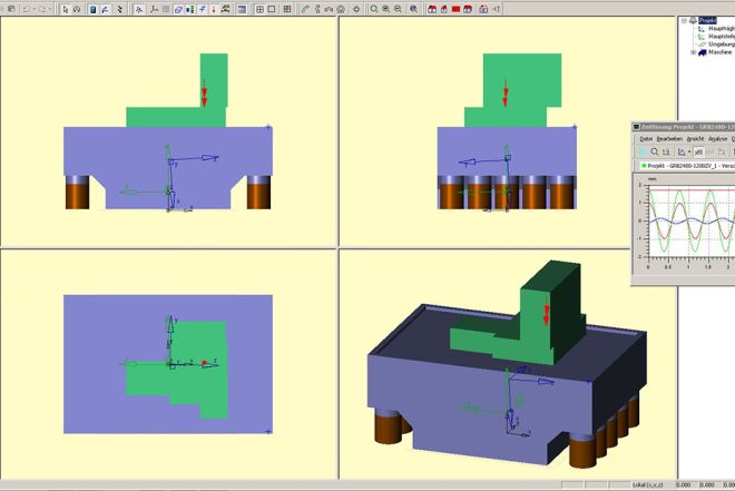
A so called frequency response analysis examines the component’s dynamic reaction to excitations in the natural frequency band. It is based on the results from the modal analysis. With this method, oscillation displacement, velocity, and acceleration are computed quantitatively. These values can be displayed as vectors for specified nodes of the FEM model. The calculation procedure is mainly offered as a service for customers, the analysis of the results is at customer’s discretion.
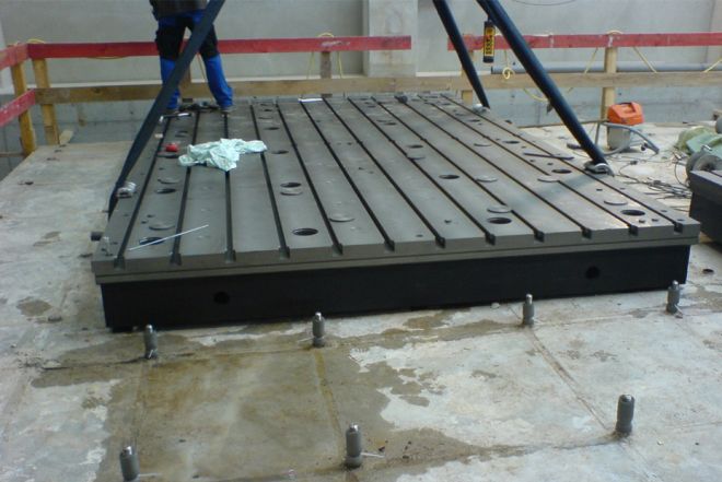
Clamping Technology
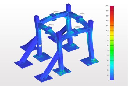
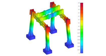
Products like clamping plates, MOCOKIT® components, foundations, and even entire assemblies are analyzed and optimized with different FEM calculations. This procedure guarantees a functioning design, particularly with newly developed, customized solutions or in applications with high frequencies and large forces. Depending on the requirements, one or multiple of the following 3 analysis procedures are applied by CFM Schiller.
The linear static analysis computes resulting stresses and deformations from given forces and moments. Computers apply principles of classic elastostatics to complex geometries while our experienced engineers evaluate these results. This analysis provides quantitative information about stiffness and strength of parts and assemblies.
A modal analysis calculates the natural frequencies and mode shapes of complex structures. If the natural frequencies of a component are too close to the frequency band, in which the test rig will operate, the part’s natural frequencies must be increased through design changes. The mode shapes are also critically analyzed by our engineers concerning the expected loads. The results are qualitatively taken into consideration for the layout.
A so called frequency response analysis examines the component’s dynamic reaction to excitations in the natural frequency band. It is based on the results from the modal analysis. With this method, oscillation displacement, velocity, and acceleration are computed quantitatively. These values can be displayed as vectors for specified nodes of the FEM model. The calculation procedure is mainly offered as a service for customers, the analysis of the results is at customer’s discretion.
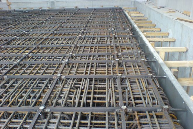
LAYOUT OF ANCHORAGE SYSTEMS
The special anchorage system from CFM Schiller is integrated into the foundation. Anchor points make a dynamically fatigue rated joint between the base plate or clamping plate and the foundation.
The layout of every anchorage system is based on the dynamic forces in every direction that act on the test rig or machine. The CFM Engineers use these specifications to determine the number of anchor points and their necessary cross-section area for the screw joint. Standard joints range from M20 to M42 while loadings of multiple meganewtons can be sustained with anchor sizes M100 or larger.
The anchorage system is dimensioned with an extremely large safety factor, without it causing a significant increase in costs. This ensures that the same fatigue rated connection can be used for other applications with higher loadings – after consultation with CFM Schiller. The special anchors transmit applied forces via very large surfaces into the surrounding concrete structure. Therefore, the concrete is never locally overloaded granting an extraordinary service life of the foundation with anchorage system.
The complete service package from CFM Schiller comprises the layout of the anchorage system, seismic mass planning, as well as selection and design of the clamping plate. For you as our customer, this guarantees that the dimensioning of the anchorage system is perfectly consistent with size and load capacity of the foundation as well as the dimensions of the clamping plate. The design of the foundation reinforcement is individually adapted to the anchorage system and installed simultaneously.