E-Mobility - Battery Abuse Testing
CFM Schiller transforms complex know-how into customized special solutions.
Thanks to our many years of experience in the field of test rig systems and special machine construction, we also off er complex solutions for battery testing. Like all test rig systems from CFM, the test rigs for battery testing are individually designed and adapted to our customers.
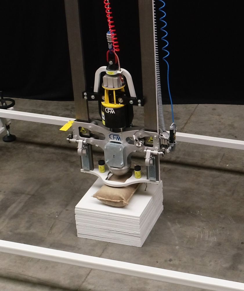
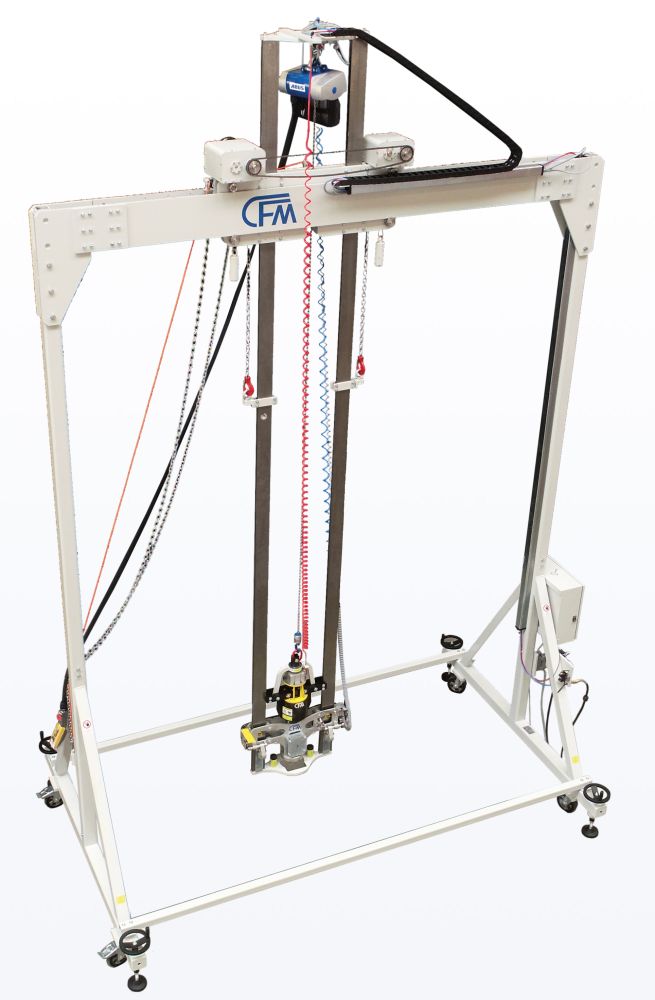
DROP TOWER TEST RIG FOR BATTERY TESTING THROUGH CRASH TESTS
The 2-column drop tower, a compact and mobile version of the 4-column drop tower from CFM's product ranges, is designed for battery testing by means of crash tests.
This drop tower consists of two vertical columns and a crossbeam on which a freely movable trolley is mounted. This makes it easy to reach any test position.
TESTING ACCORDING TO
» IEC 62281:2016 RLV
» UN38-3
The special feature of the drop tower is the guided fall, particularly in the impact area. The possible energy of the impulse load results from the drop height and mass of the so-called impactor and from the test setup. The drop tower consists of a steel structure up to approx. 3700 mm high with two high-precision guides. The steel structure with its high-precision guide columns enables the impactor to fall in a guided manner via its roller units with minimal resistance. A locking mechanism catches the impactor after the fi rst impact. This ensures that no second impact falsifies the result.
TECHNICAL DATA
Drop height (adjustable)
100-2500 mm
Drop weight
20.8 kg plus max. additional weight
20 kg (in 1 kg increments)
Impactor
Hemisphere diameter 170 mm or
180 mm
Impact energy: 20 J-1000 J
Mechanical anti-kickback device to prevent a second impact
Size
Length: 3700 mm
Width: 2260 mm
Height: max. 6205 mm
Optional
Velocity measurement of the impactor shortly before impact.
Transverse adjustment of the impactor using a cable pull.
Height adjustment of the impactor drop guard using a chain hoist.
Release mechanism
• Fully automatic
• Pneumatically controlled
• Electrically monitored
• Redundant release protection
Lifting of the impactor via chain hoist.
Operation via control cabinet and manual control panel with cable connection
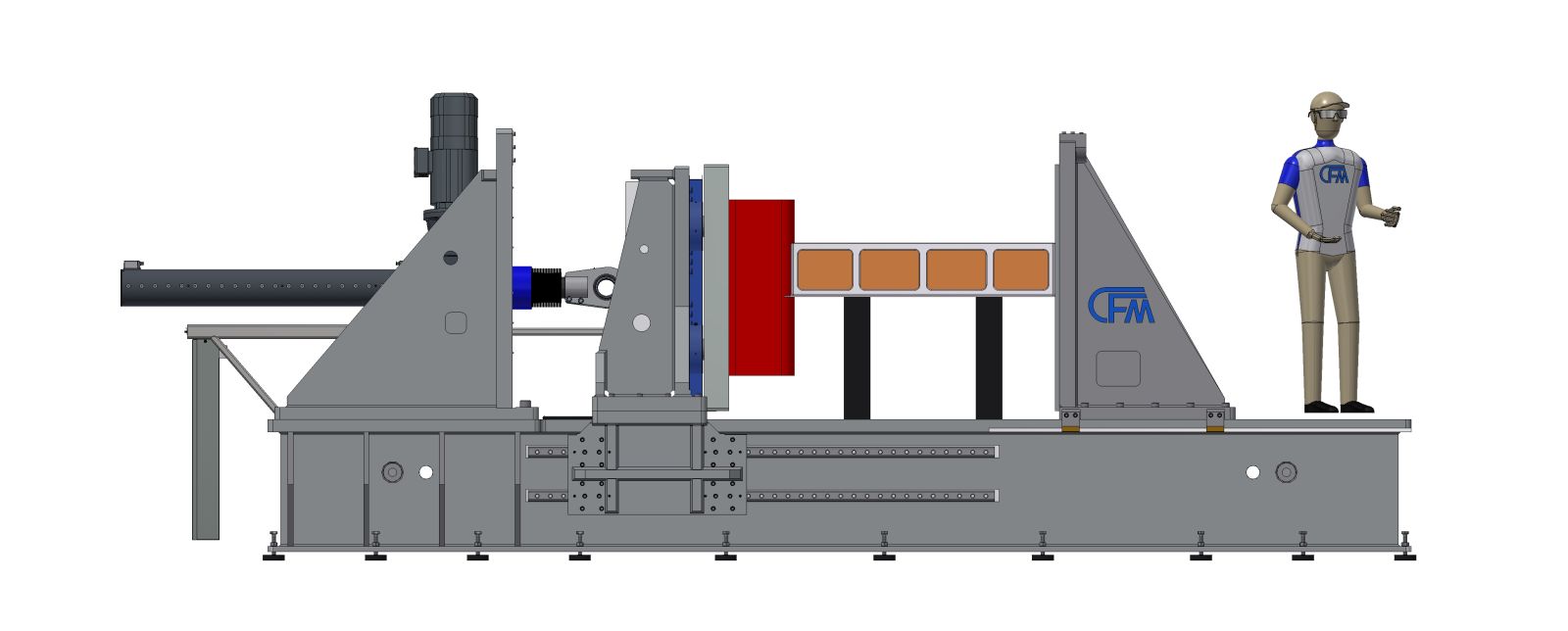
CFM CRUSH TEST RIG 500 KN
BATTERY ABUSE TESTING
The CFM crush test rig for testing the mechanical integrity of batteries / high-voltage storage systems is used to examine cells, modules and
complete high-voltage storage systems. Compression and crush tests can be carried out by load or displacement control.
The CFM crush test rig consists of a base frame in a highly rigid design, a longitudinally adjustable reaction bracket with threaded hole pattern and the electro-mechanical crush unit. The electro-mechanical crush unit consists of a very rigid mounting bracket for the electro-mechanical actuator, a compression frame mounted in precision guides, the load cells and the pressure plate. Various crush plates can be mounted on the pressure plate.
The crush plates according to UNECE R 100 and GB/T31467.3-2015 are available as accessories.
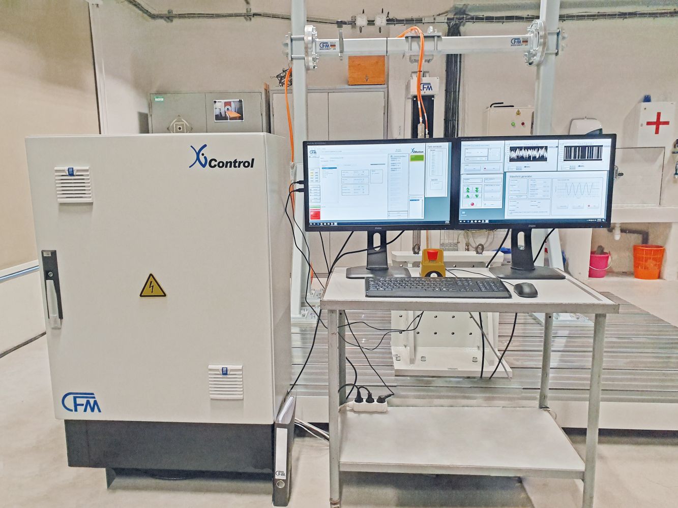
The CFM controller XiControl with the software package XiMotion is used to control the CFM crush test rig. The XiControl is a universal digital controller for test applications, enabling functions including displacement and load control. The XiControl controller can be used with linear actuators (electric or hydraulic) as well as with rotary actuators or electric machines.
CRUSH TEST OF HIGH-VOLTAGE BATTERIES ACCORDING TO
» UNECE R 100
» SAEJ 2464:2009
» GB/T31467.3-2015
The XiControl has a clock frequency of 2.5 kHz, analog measuring inputs, strain gauge measuring inputs and analog outputs. Various signal functions are available on its function generator. ± 10 V analog outputs are used to control the actuators. Using the XiControl controller and XiMotion software, the crush test rig can be operated in both displacement and load control modes. Test sequences can also be pre-programmed. The compression, holding and retraction procedures can be freely configured. Forces and displacements are recorded synchronously during the test sequence. It is also possible to record additional measured values and also record a synchronized video.
TECHNICAL DATA
Length:
7335 mm
(6500 mm base frame)
Width:
1920 mm
Height:
2640 mm
(2450 mm without drive)
Weight:
34 t
Crushing force:
500 kN (Optionally up to 1500 KN)
Crushing speed:
max. 10 mm/s
Max. actuator stroke:
1500 mm
Number of load cells:
four (4)
Max. size of the test specimen
(without crush plate):
3000 x 1400 x 1400 mm (l × w × h)
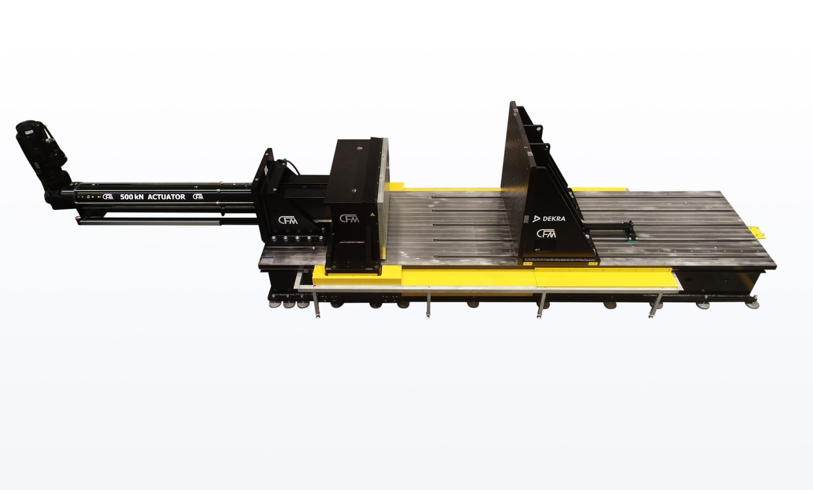
500 KN CRUSH TEST RIG
TECHNICAL DATA
Length: approx. 8885 mm (6135 mm base frame)
Width: approx. 1920 mm
Height: approx. 2165 mm (2075 mm without drive)
Weight: approx. 23 t
Crushing force: 500 kN
Crushing speed: max. 10 mm/s
Max. actuator stroke: approx. 1500 mm
Max. size of test specimen:
3400 x 2200 x 500 mm (l × w × h)
CRUSH TEST OF HIGH-VOLTAGE BATTERIES ACCORDING TO
» GB 38031-2020
» UNECE R100
» SAE J2464
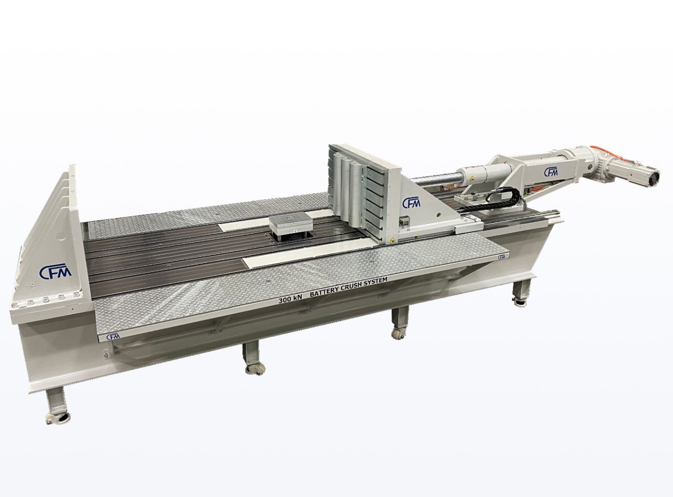
300 KN CRUSH TEST RIG
WITH 2ND CHANNEL FOR NAIL PENETRATION TEST
TECHNICAL DATA
Length: approx. 6,090 mm (5,040 mm base frame)
Width: approx. 2,200 mm (1,250 mm base frame)
Height: approx. 1,755 mm
Weight: approx. 8.5 t
Crushing force: 300 kN
Crushing speed: max. 10 mm/s
Max. actuator stroke: approx. 1,000 mm
Actuator load nail penetration test: 50 kN
Actuator speed nail penetration test:
max. 20 mm/s (at 50 kN; max. 80 mm/s at 10 kN)
Max. actuator stroke: approx. 400 mm
Max. size of test specimen:
3,200 x 2,200 x 700 mm (l × w × h)
CRUSH TEST OF HIGH-VOLTAGE BATTERIES ACCORDING TO
» GB 38031-2020
» UNECE R100
» SAE J2464
300 KN CRUSHING DEVICE
TECHNICAL DATA
Length: approx. 6,340 mm (4,805 mm base frame)
Width: approx. 1,700 mm (1,250 mm base frame)
Height: approx. 1,950 mm
Weight: approx. 9 t
Crushing force: 300 kN
Crushing speed: max. 10 mm/s
Max. actuator stroke: approx. 1,000 mm
Max. size of test specimen:
3,000 x 1,700 x 700 mm (l × w × h)
CRUSH TEST OF HIGH-VOLTAGE BATTERIES ACCORDING TO
» GB 38031-2020
» UNECE R100
» SAE J2464
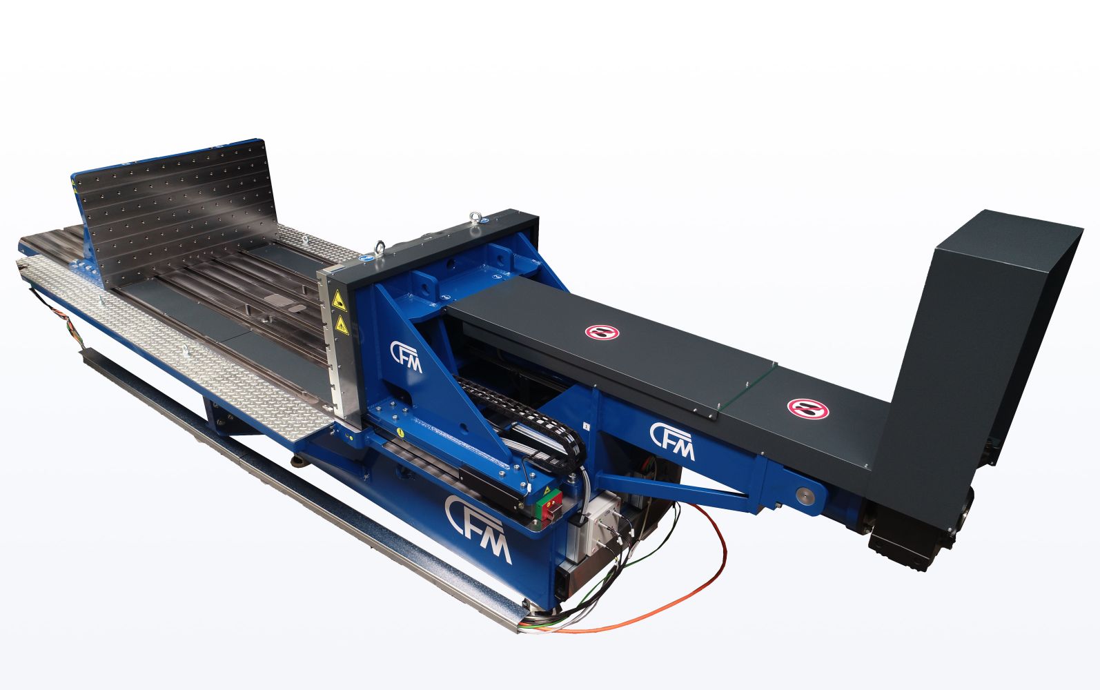
FUEL FIRE TEST RIG
The CFM fuel fire test rig is used to test the fire resistance of rechargeable electrical energy storage systems or subsystems thereof. The test specimen is exposed to fire under various, defined conditions according to UNECE R100.
The CFM fuel fire test rig is built on a base frame made of steel beams. The drives for the test bench's movable elements are integrated into the approximately 11.2 m long base frame. The movable elements - test specimen holder, fire screen and cover - move on the frame, which enables easy and precise positioning. The individual elements are moved using chain drives attached to both sides, which are driven by gear motors. The movable test specimen holder consists of a stiff ened steel frame with a manually height and width adjustable holder frame. The battery is suspended from this. The height can be adjusted in a range of approx. 250 - 1,100 mm from the top edge of the fire bowl. The fuel pan consists of a base frame that can be fitted with a forklift attachment. The fuel pan is designed as a steel pan with a height of 60 mm. Smaller individual pans can be inserted into the fuel pan to divide the fired area and adapt it to the size of the test object. Like the large fire pan, each individual pan is equipped with a closable drain. The fuel is ignited remotely using electrically controlled disposable igniters.
The base frame of the movable fire screen is also made of steel and is equipped with welded T-profiles at a distance of 242 mm and a support width of 10 mm, in accordance with the standard, so that firebricks of type FFP-ECE R34 (240x120x70mm) can be inserted and replaced if necessary. In order toextinguish the fire in the fire bowl after the test if necessary, a telescopic extinguishing cover made of steel is installed, which is pulled over the fire bowl after the test and thus smothers the fire. All steel components are painted with temperature-resistant thermal paint. The test bench is controlled by a PLC, which allows the fully automatic movement of all driven axes to stored positions. Since the electric drive motors are operated with a frequency converter, the travel speeds of the individual movable elements can be adjusted. The test bench is operated using a hand-held control panel with an integrated Siemens KTP 700 display.
TECHNICAL DATA
Length: 12200 mm
Width: 2950 mm
Height: 1725 mm
Weight: 4,5 t
Fuel pan dimensions (L x W x H): 3560 x 2450 x 60 mm
Fire screen dimensions (L x W x H): 3490 x 2650 x 75 mm
Dimensions of extinguishing cover (L x W): 3600 x 2500 mm
Dimensions of test specimen holder (L x W): 3400 x 2500 mm
Max mass of test specimen: 1200 kg
» Remote controlled, electric fuel ignition
» Hand control panel (Rose Limanda ) with Siemens KTP 700 touch panel (wired)
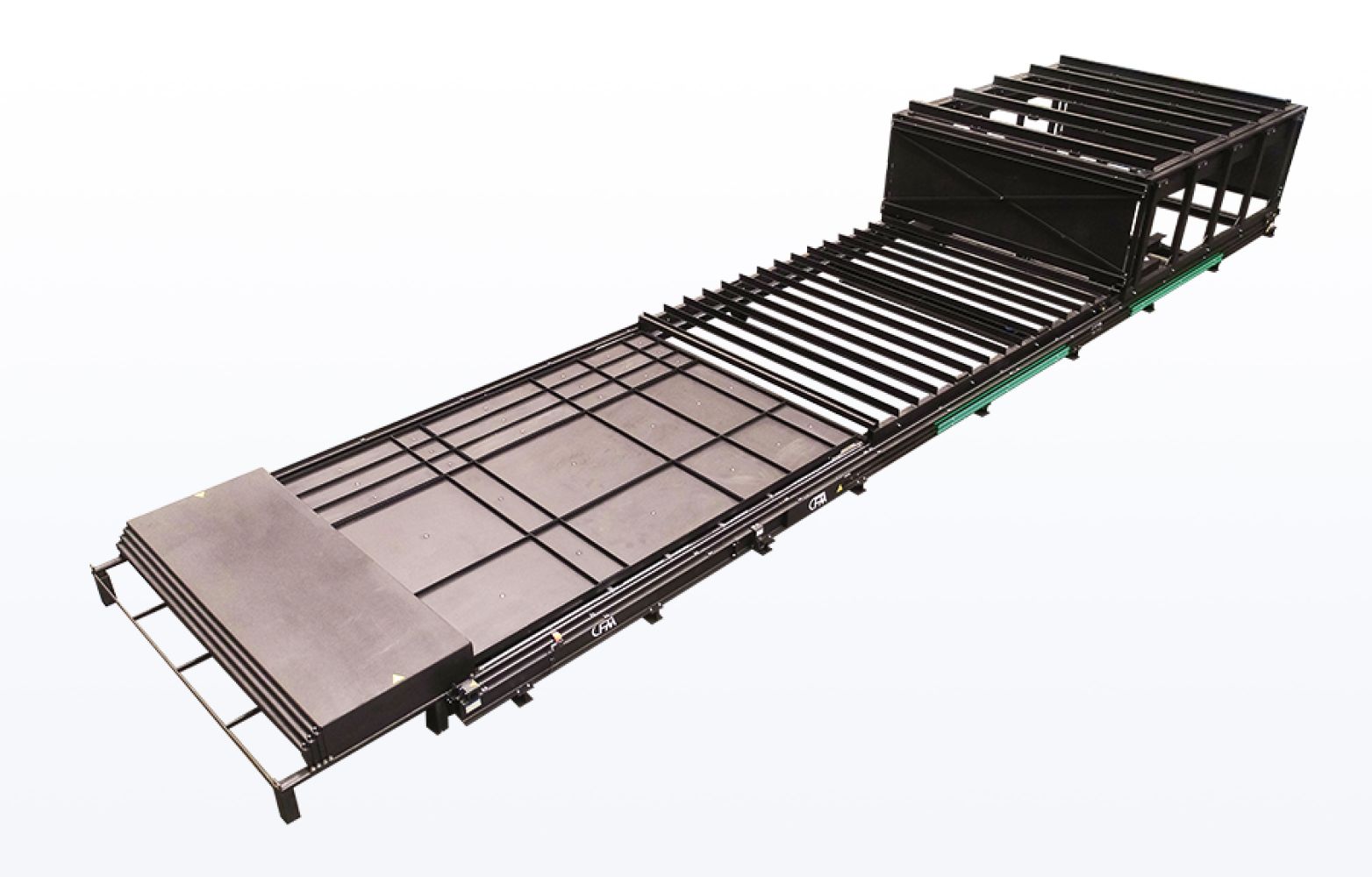
HIGH-VOLTAGE STORAGE FIRE TEST RIG
The fuel fire battery test bench is used to carry out fire tests on high-voltage vehicle batteries in accordance
with the requirements of UN ECE R 100. The aim is to investigate the behavior of batteries under realistic fire conditions and to evaluate safety-relevant properties. This test can be carried out on the test bench with both gasoline and liquid gas.
The test stand consists of a modular base frame made of steel beams. Stainless steel guides are mounted on the frame, on which both the fire screen and the test specimen holder can be moved. The drives are provided by SEW geared motors. All steel components are painted with temperature-resistant black paint.
The test specimen holder is a movable frame made of heat-resistant steel, which is mounted on castors. It is equipped with a height-adjustable support frame that carries a grating made of 8 mm thick stainless steel bars. The grating is interchangeable and designed for a maximum load of approx. 1000 kg. The maximum possible projected test specimen area is 3800 x 3280. The height adjustment is carried out manually using a forklift truck and can be locked in 50 mm increments so that the height of the test specimen above the fi re bowl or the liquid gas burners can be adjusted.
During the test, the test specimen can be moved over the flames of the fuel fire in the frame after the heating phase and returned to the starting position after the required exposure time.
TECHNICAL DATA
Length: approx. 12.000 mm
Width: approx. 3.500 mm
Height: approx. 2.600 mm
Weight: approx. 13 t
Burner surface dimensions (L x W): approx. 3.500 x 2.700
Fire screen dimensions (L x W x H): approx. 4.200 x 3.060 x 340
Test specimen holder dimensions (L x W): approx. 3.800 x 3.280
Max mass of the test specimen: approx. 1000 kg
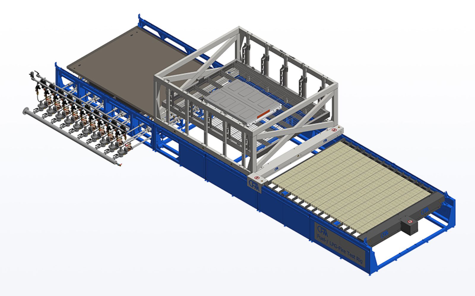
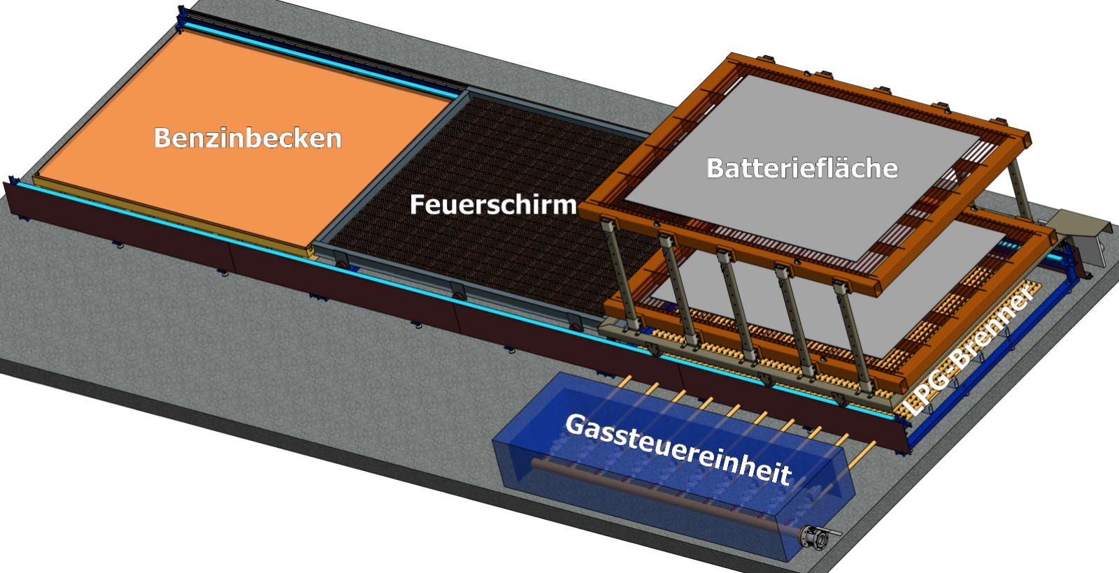
COMBINED FIRE TEST BENCH WITH LPG BURNERS – LPG FIRE TEST RIG
The CFM combined fire test bench includes a burner surface with a propane gas burner system (LPG).
This allows not only to control the fl ame exposure also the UNECE R100 and the KMVSS (Annex 1 -Part 48) can be fulfi lled. The burner system consists of 9 atmospheric burner segments, which are divided over an area of 3,400 x 2,400 mm. The burner segments are each divided into 5
burner strips and are each ignited by an individual igniter and monitored at the end by an ionization electrode. The ignition is electrically realised. The burner system complies with DIN 746 Part 2 for thermal processing systems. Each burner segment includes a manually lockable ball valve, two electric gas shut-off valves and an electrically controlled gas flow regulator (DN 32). The test bench has a separate control cabinet for valve, regulator and ignition control as well as monitoring of the burner segments. The burner control also reports burner segment errors. The flame characteristics can be influenced by the electrically controllable pressure regulator. The burner bars are mounted on a steel base frame that is painted with temperature resistant coating. The gas consumption is approx. 750 kg/h.
TECHNICAL DATA
Length: 11500 mm
Width: 3380 mm
Height: 2050 mm
Weight: 19 t
Dimensions of burner surface (L x W):
3400 x 2400
Dimensions of the fire screen (L x W x H):
3600 x 2650 x 140
Dimensions of test specimen holder
(L x W): 3400 x 2500
Max mass of test object: 800 kg
Total burner output:
9500 kW
Flame height:
60 cm
Fuel:
Propane
Gas inlet pressure:
100 mbar
- Monitoring of the ignition bar (9×)
- Remote-controlled, electrical ignition of the burner bar
- Hand control panel (Rose Limanda) with Siemens KTP 700 touch panel (wired)
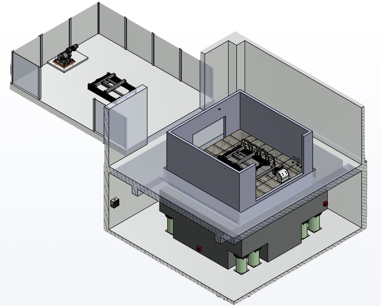
EVACUATION SYSTEM FOR BATTERY TESTING
High-voltage batteries for motor vehicles play an important role in the emission-free mobility of the future. Multi-axial servo-hydraulic vibration tables with a climate chamber are used to test these HV storage systems. These simulate vehicle movements in all six degrees of freedom under extreme temperatures and electrical loads.
In the event of an accident, rapid evacuation is required to prevent damage to the climate chamber and the test stand. Automatic evacuation is required to minimize the risk of personal injury.
For this reason, CFM supplies evacuation systems for removing the damaged test specimen from the test chamber, in addition to the vibration foundation on CFM air springs.
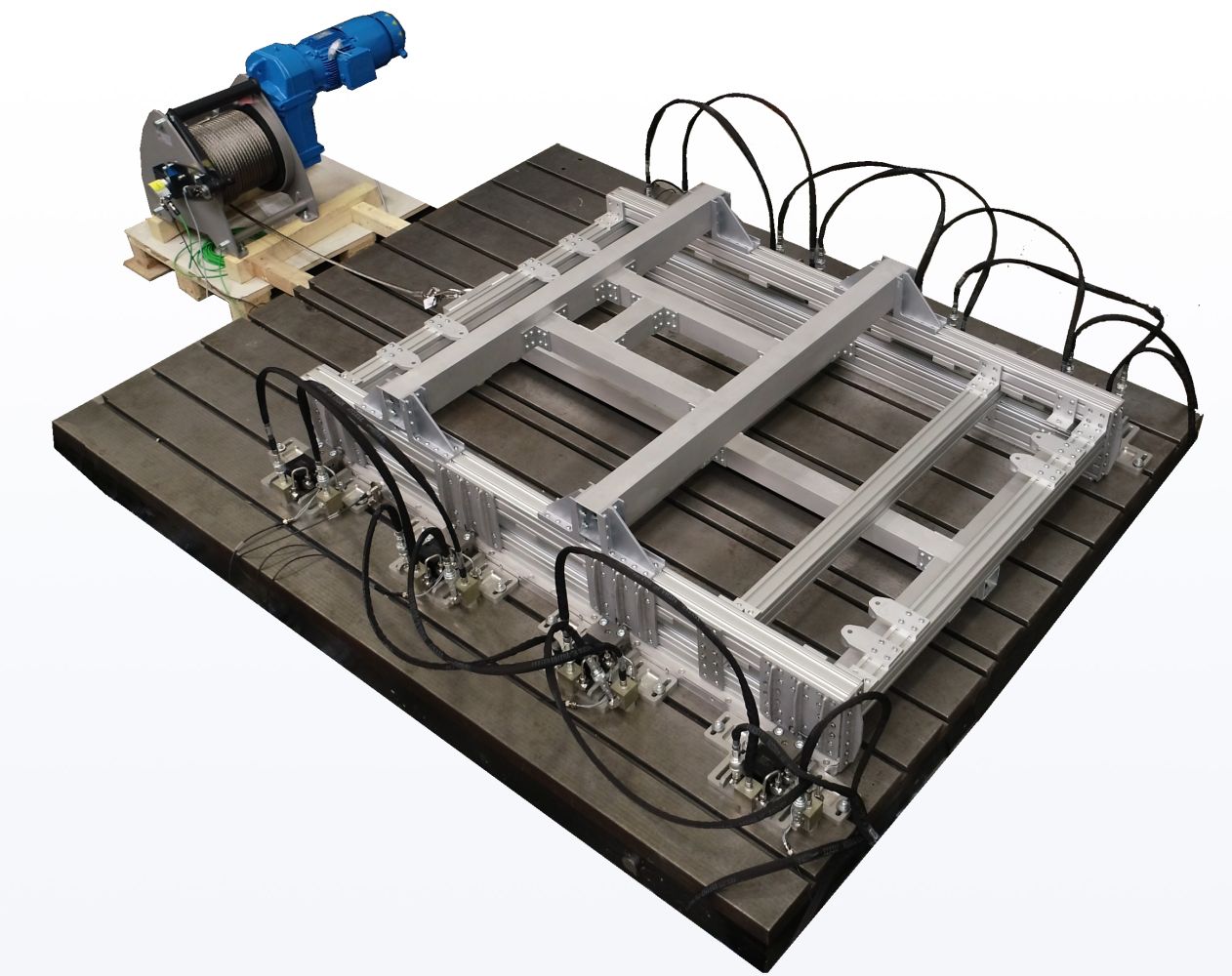
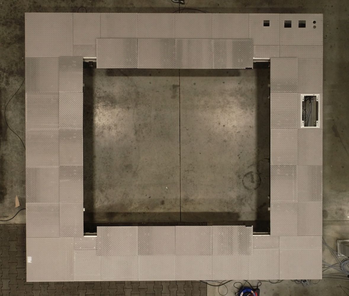
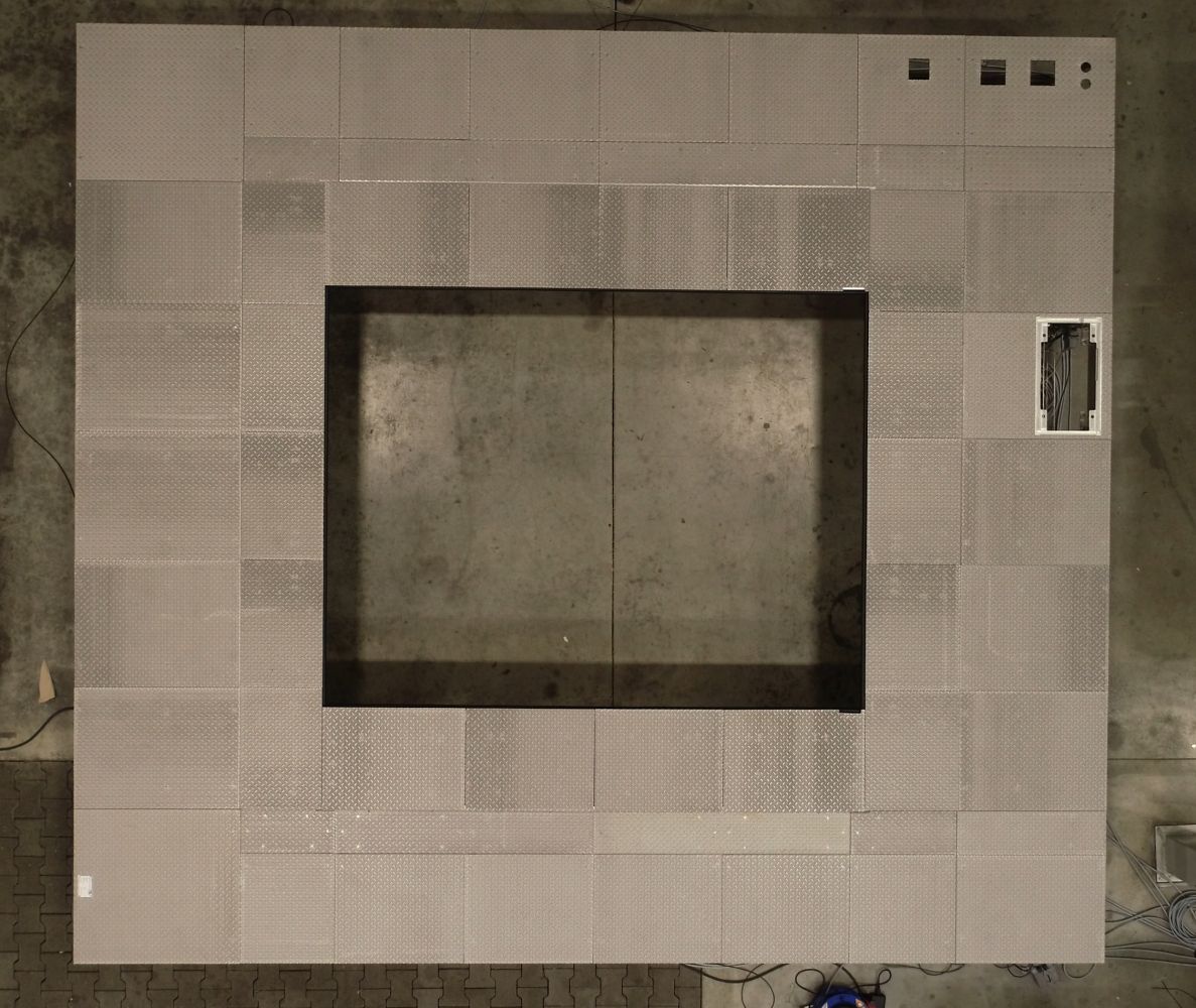
The evacuation system consists of a raised fl oor, a clamping system with test specimen pallet and a winch system. The raised floor is placed on the floor of the climate chamber and forms a level at the height of the table surface in the minimum position. It is equipped with electrically extendable segments around the simulation table. These are retracted during test operation to provide the necessary clearance for the oscillating table movements. In the event of an accident or to ensure convenient access to the test specimen, the elements are moved back towards the table so that the surface is closed. The automatic cover is designed to be weight-optimized and corrosion-protected. The electric cylinders for opening and closing the cover are also suitable for use in the climate chamber.
The clamping system clamps the pallet, which serves as a support for the test specimen, to the oscillating table so that the mechanical test loads can be applied. In the event of an evacuation or for normal set-up work, the hydraulic clamping is automatically released and the pallet and battery can be pulled out of the chamber using the winch.
The pallet is then pulled into a basin or a safe area so that the battery can burn off in a controlled manner.
PROCEDURE OF THE EVACUATION
» The oscillating table moves to the minimum position (not via CFM control)
» The cover is closed (via CFM Control system)
» The hydraulic clamping elements release the pallet (via CFM control)
» All cables and hoses to the battery are disconnected (not via CFM control unit)
» The air conditioning chamber door is opened (not via CFM control)
» The pallet is pulled out of the chamber with the winch chamber (via CFM control)
TECHNICAL DATA
- Designed for multiaxial oscillating tables with a permissible load of 1,000 kg
- Dead weight of clamping system approx. 110 kg
- Inner surface of the climate chamber typically
approx. 5,000 x 4,500 mm - Circumferential gap with retracted cover
approx. 300 mm - Temperature range approx. -40 - +90°C
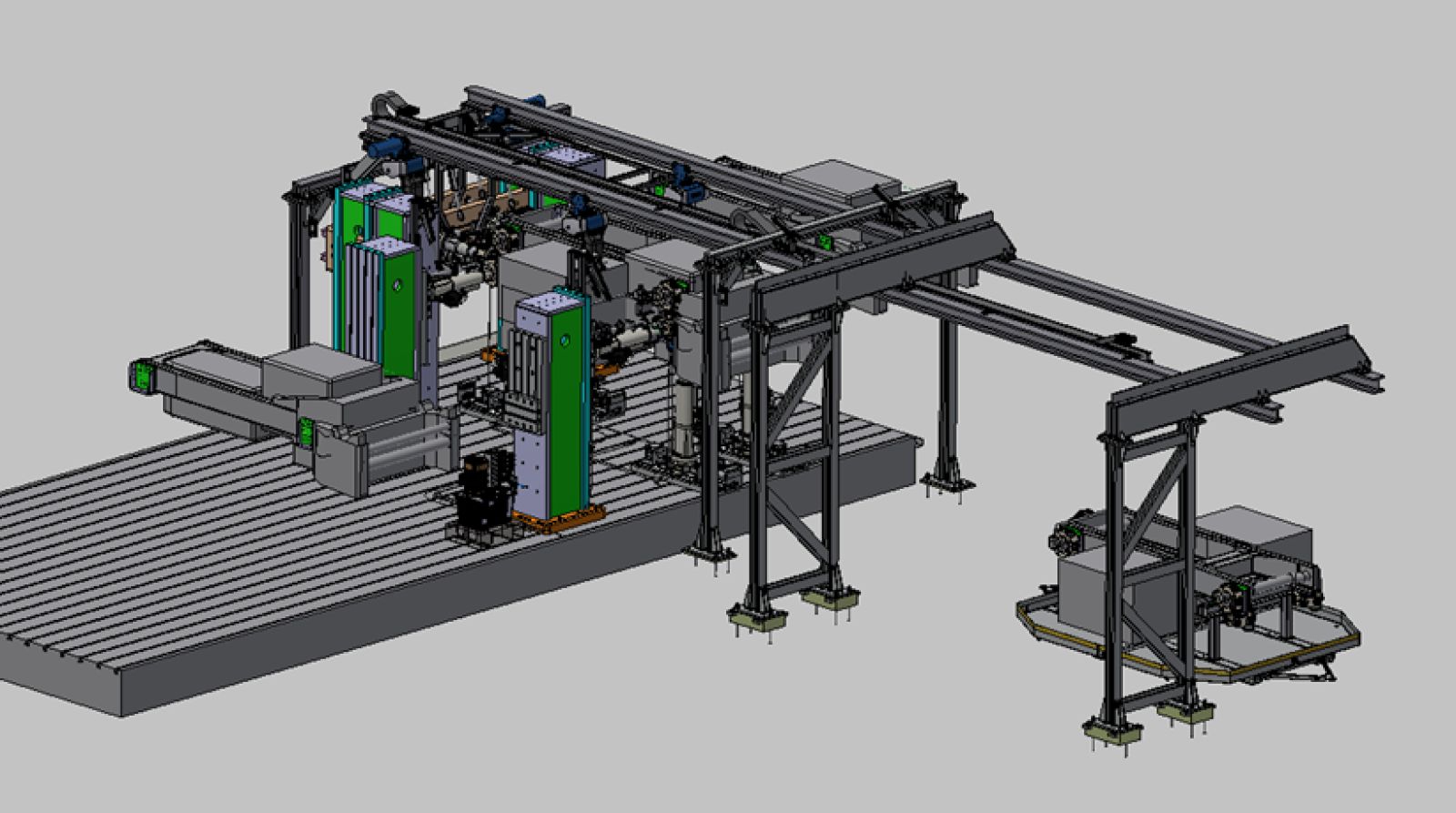
EVACUATION SYSTEM FOR HIGH-VOLTAGE BATTERY TESTING WITH COMPONENT TEST BENCHES
If an add-on or component test stand is used to test high-voltage batteries or other flammable components for trucks or passenger cars, evacuation with a cable winch is generally not possible, as the actuators must be firmly connected to the test specimen.
Nevertheless, in the event of an accident, rapid evacuation is necessary to prevent damage to the test bench and the test chamber. To minimize the risk of personal injury, automatic evacuation is also required here.
CFM therefore also delivers evacuation systems for add-on or component test benches with any number of channels or actuators to remove the damaged test specimen from the test chamber.
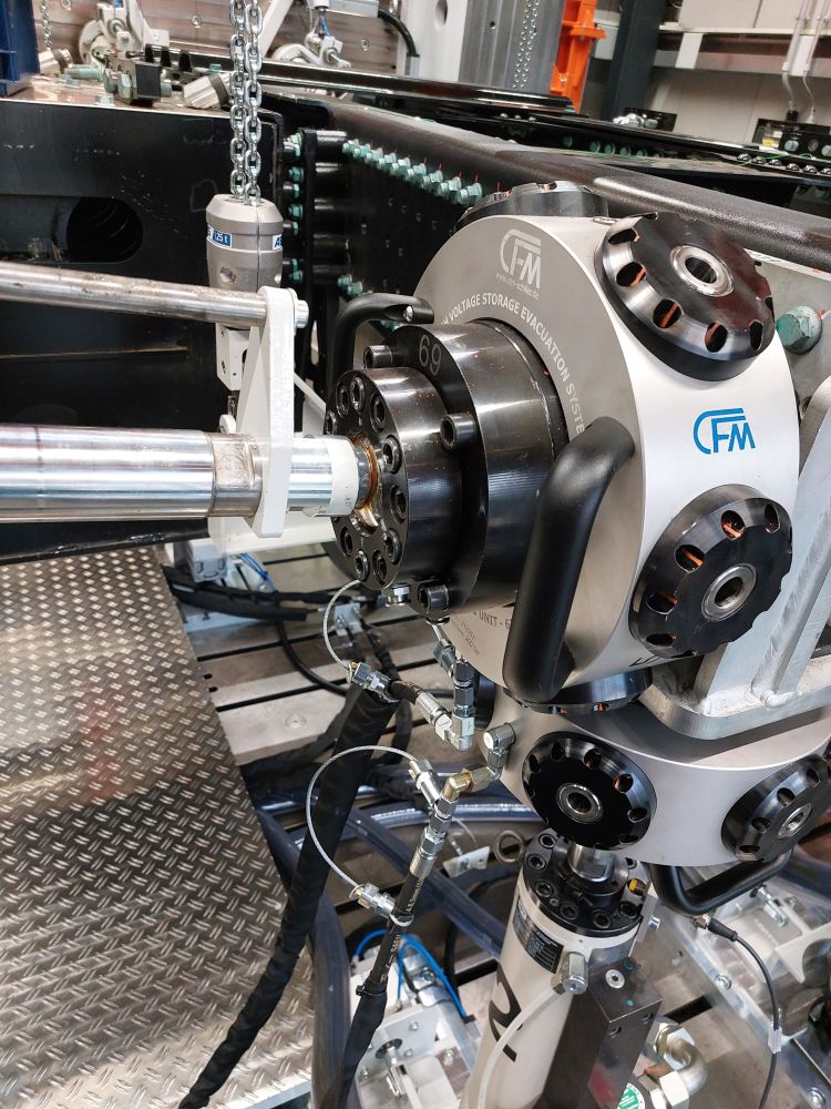
The evacuation system consists of our patented locking and unlocking units on the ball joints on the cylinder rod, an adapter plate as a counterpart on the test specimen, automatically movable chain hoists including electrically driven trolleys as well as various pneumatic and electric actuators and a customized steel construction of the split crane runway. This is located above the test area and extends into the secured area.
During normal operation of the test bench, the evacuation system is in a standby state and all moving parts are parked in non-critical positions to provide the necessary space for the movements of the test bench. Only the locking units are in direct contact with the test bench and ensure the connection to the test specimen - due to the high preload force, the entire force is transferred directly from the actuators to the test specimen without any losses. The units are designed as a mechanically clamping system that is unlocked hydraulically.
In order to be able to move the test specimen, four partly mechanically coupled trolleys including hoists and drives are used. These are mounted on a split evacuation track that closes automatically in the event of an evacuation. This allows the test specimen to be moved into the secured area outside the test chamber after unlocking.
To prevent vertically installed actuators from tilting, a pneumatically operated locking mechanism can be provided. Electric actuators can be used to support the horizontal cylinders.
All actuators are equipped with limit switches and sensors, which enables safe and automatic operation - both in the event of an emergency and for setting up the test bench.
Evacuation process
The test bench moves to the zero position (test bench control)
The chain hoists move the switched-off test bench to the centre position
The hydraulic locking and unlocking units release the test specimen and are supported if necessary
The hall door is opened, the crane runway is closed
The test specimen is lifted and moved to a safe position
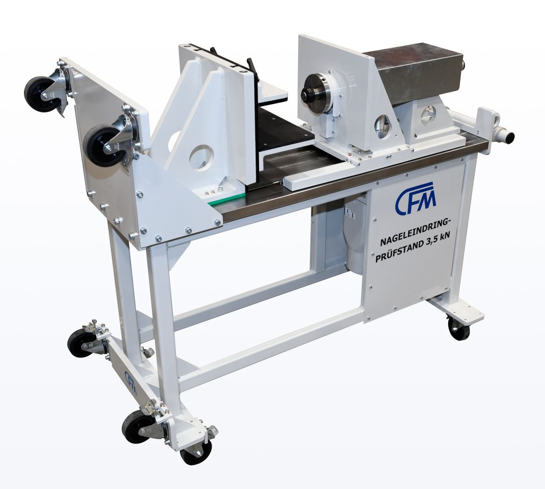
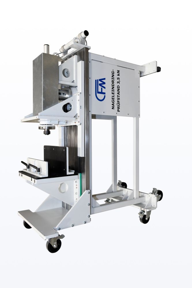
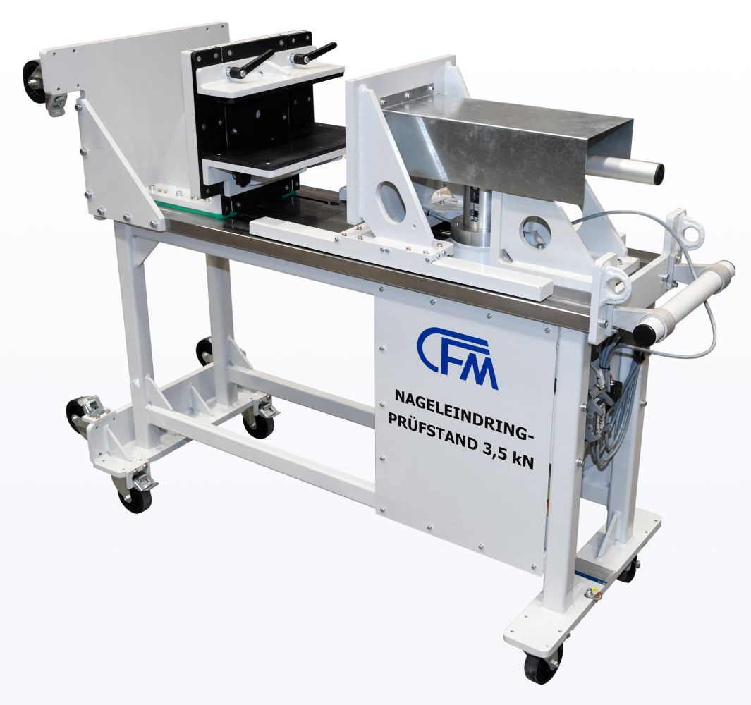
NAIL PENETRATION TEST RIG 3.5 KN
The CFM nail penetration test bench is used to perform nail penetration tests in horizontal or vertical positions on battery cells or modules for electric vehicles.
The battery nail penetration test system essentially consists of a table, an angle bracket for fixing the actuator, a counter angle bracket, and a “crushing angle bracket” which is equipped with guides and a nail holder connected by means of a load cell.
The machine table is designed as a welded steel construction and serves to achieve a comfortable working height. Its upper surface is machined in accordance with DIN 876/III and equipped with two T-slots in the longitudinal direction in accordance with DIN 650 12H12. In addition, the top of the table has precision surfaces for mounting precision linear guides. These are protected by cover plates.
The counter angle is equipped with two T-slots on the front side in accordance with DIN 650 12H12 and plastic plates for electrical insulation. A height-adjustable retaining bracket for the test specimen and a counterholder, which is also height-adjustable, are clamped into the T-slots of the bracket. These brackets are also fitted with plastic plates on the contact surfaces to the test specimen.
The actuator is a ball screw lifting element with a stroke of 200 mm. It is electrically driven by a gear motor with a fl anged servo drive. The actuator speed is infi nitely variable. The position measurement accuracy is ≤ 0.5%.
The CFM XiControl controller with the XiMotion software package is used to control the CFM nail penetration test bench. The XiControl controller is a universal digital controller for testing machines that enables displacement and force control, among other things.
Technical Data
» Length: approx. 1576 mm
» Width: approx. 600 mm
» Height: approx. 1205 mm
» Weight: approx. 415 kg
» Penetration Force: max. 3.5 kN
» Movement Speed: max. 100 mm/s
» Specimen dimensions:
600 x 200 x 200 mm
Testing according to the standard:
» UN ECE-R100