Combined pendulum impact / roof load test rig
for truck cabs in accordance with ECE R29/3 Suppl. 5, VVFS 2003:29 and relevant impact standards
Our vehicle safety test rig systems are characterised by their precise design, robust construction and maximum adaptability – developed for demanding test tasks in the commercial vehicle industry.
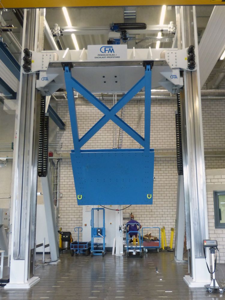
The combined test rig integrates roof load and pendulum impact testing into a single system. This allows standard-compliant tests as well as extended testing of the structural integrity of cabs under static and dynamic loads.
The system is designed around a 2-column load frame structure with a height-adjustable crossbeam, offering a flexible solution to meet diverse test requirements. The crossbeam can be moved at a speed of up to 680 mm/min and allows for precise positioning with an accuracy of < ± 0.5 mm – both in jog mode and via defined target positions using a mobile remote control.
Two manually adjustable clevis brackets are mounted on a T-slot rail below the crossbeam. These can be moved horizontally and are mechanically clamped. In addition, integrated through-holes allow for the quick installation of pressure plates for roof load testing.
Roof load tests
Roof load tests are carried out in accordance with ECE R29/3 Suppl. 5 and VVFS 2003:29 by moving the cross-beam in force-control mode.
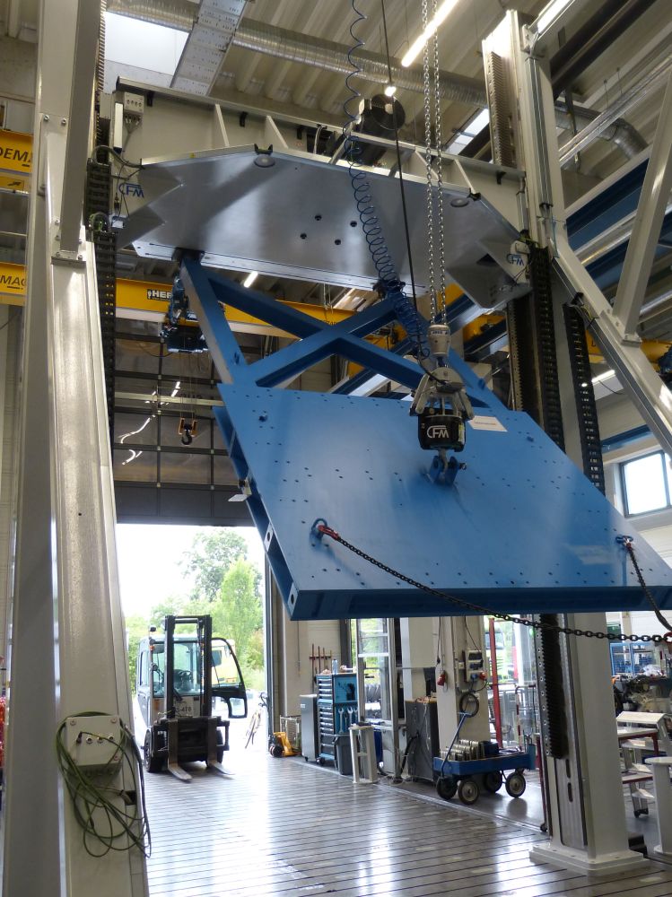
A pressure plate, mounted beneath the cross-beam, is equipped with four load cells, ensuring uniform and precise force application. The maximum roof load is 150 kN.
To accommodate lateral forces and moments that may arise from the structure of the cab, the two columns are designed to compensate for moments of up to 150 kNm. The mounting surface, measuring approximately 3,000 x 2,000 mm, facilitates the flexible installation of various test plates.
Pendulum impact tests
For conducting pendulum impact tests, the crossbeam is automatically clamped via hydraulically released spring-loaded clamping cylinders.
The system complies with the requirements of the relevant impact standards, including ECE R29 (pendulum impact test) and OEM-specific and international test specifications.
The winch for deflecting the pendulum is mounted at a 2D positioning system, which facilitates precise electric adjustments in both the X and Y directions. This ensures the precise positioning of the release mechanism.
The mechanical-pneumatic release mechanism, located beneath the trolley, allows for precise positioning, secure holding, and controlled release of the pendulum. The release angle and drop height are calculated, displayed and automatically adjusted according to the length of the pendulum.
The system is designed for a maximum drop weight of 2,800 kg (at 90° deflection) and features a multi-stage safety system with primary release and mechanical safety claws. The required compressed air supply is 6 bar.
Control system
To control the test rig the CFM XiControl control system is used in combination with the XiMotion software.
The system is based on high-performance PID controllers that enable both force- and position-controlled test sequences. Additionally, the software allows the integration and operation of a Siemens PLC within a unified user interface. This offers a very user-friendly operation in hybrid systems where both simple positioning axes and controlled axes are operated.
Your benefits at a glance
- Combination of roof load and pendulum impact testing in a single system
- Tests compliant with ECER29/3 Suppl. 5, VVFS 2003:29 and ECE R29
- High structural rigidity and ability to compensate large forces and moments
- Precise, reproducible positioning and load control
- Modular design for different cabin geometries
- Integrated flexible control system
- Designed for demanding development and validation tests